|
 ABOUT / TUTORIALS
 '64-'72 FORD TRUCK MPC
 GENERAL
INFORMATION
 CHASSIS PARTS
- INDEX
 PAINT SECTION
 SECTION 10 INDEX
 SECTION 20
INDEX
 Section 20
 Section 20.1
 Section 21
 Section 22
 Section 22.1
 Section 22.2
 Section 23
 Section 23.1
 Section 24
 Section 26
 Section 28
 SECTION 30
INDEX
 SECTION 40
INDEX
 SECTION 50
INDEX
 SECTION 60
INDEX
 SECTION 70
INDEX
 SECTION A70
INDEX
 SECTION T70
INDEX
 SECTION 80
INDEX
 SECTION 90
INDEX
 SECTION 100
INDEX
 SECTION 110
INDEX
 SECTION 120
INDEX
 SECTION 130
INDEX
 SECTION 140
INDEX
 SECTION 160
INDEX
 SECTION 170
INDEX
 SECTION 180
INDEX
 BODY PARTS -
INDEX
 SOFT TRIM PARTS -
INDEX
 CROSS REFERENCE
LIST
|
SECTION 22
| 2225 — CHAMBER ASSY. - REAR
BRAKE AIR - continued |
| 1970/ MODEL APPLICATION How to use this chart:
- Determine the truck model (use the truck warranty number
prefix and the General Information Section of this catalog).
- Determine the rear axle capacity (use the warranty plate
rear axle code and Section 40.1 of this catalog.
- Determine the brake type - wedge or cam. (See the
explanatory note at the bottom of this page).
- Determine whether the truck has a spring-set parking brake
(ask whether the truck has a control located on the dash for a
spring-set air parking brake)
- For tandem models, determine whether the truck has a tractor
package (ask whether it has trailer brake hoses).
- For some tandem models, determine the suspension. (See
tandem suspension illustrations in Illustration Section 55),
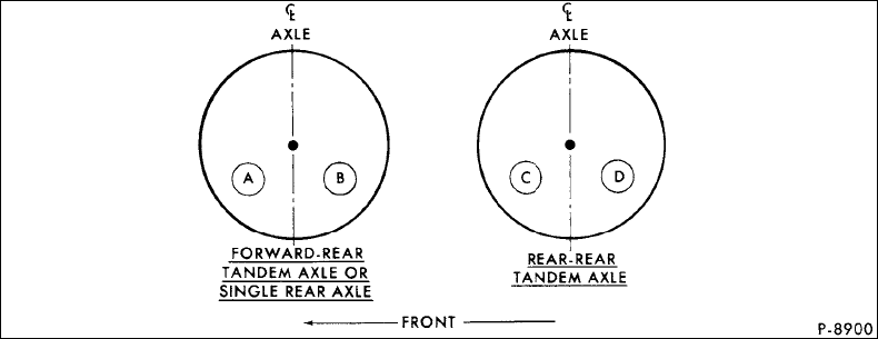
- Determine the location of chamber (use location diagram
below).
- Select the part number. (Single axle trucks use 4 wedge-type
chambers or 2 cam-type chambers and tandem axle trucks use 8
wedge-type chambers or 4 cam-type chambers).
- To repair a chamber, first find the chamber assy. part no.
in the Model Application listing. Next, note the Parts List
number, which appears next to the "Loc. & Qty." column. Finally,
find the Parts List in Section 22.2.
- Illustrations of brake chamber components appear in
Illustration Section 21.
- Illustrations of brake chambers appear on pages
14 and 15 to
aid identification.
|

 - W - Wedge-type brakes, C - Cam-type brakes. Wedge brakes use 2 chambers
for each wheel (attached to brake carrier plate); Cam brakes use 1 chamber
for each wheel (attached to bracket on axle housing)
S/S - Spring-set
 - Refer to location diagram above. The quantity (per axle) is always two
for each letter. Example: A=2, B=2, AB=4.
 - Refer to Section 22.2 for Chamber Parts Lists.
% - Details not provided for service for Wagner Electric or
Midland-Ross types.
 - E -
Wagner Electric, G - Gustin Bacon, H - Bendix-Westinghouse, L - Anchor Lok,
M - MGM brakes, R - Midland-Ross - E -
Wagner Electric, G - Gustin Bacon, H - Bendix-Westinghouse, L - Anchor Lok,
M - MGM brakes, R - Midland-Ross
$ - Refer to Illustrations on pages 14 & 15.
Sizes shown on page 16.
NOTE 3 - Marked "C1" on outside of the chamber cylinder
NOTE 4 - Marked "D1" on outside of the chamber cylinder
|