|


|

|
|
|
Installing a Factory A/C Unit |
|
|
 |
NOTE: THIS TUTORIAL IS CURRENTLY UNDER CONSTRUCTION.
It will be updated in the near future with more detailed information and
better reference pictures as I complete the A/C installation on my own
truck.
|
|
With
more and more of the '67-'72 trucks being taken off the roads as
a utilitarian workhorse and being rebuilt as an everyday cruiser
or daily driver, comfort becomes more of an issue than when the
truck first rolled off the assembly line. Adding
air-conditioning (A/C) to a truck not so equipped from the
factory has become a fairly common upgrade. This purpose of this
tutorial is to provide you with reference photos and info necessary to
install a factory A/C setup in your truck. I'll be installing a
factory setup in my own project truck in the near future and
will be updating the installation procedures detailed below with
the proper wire hook-ups.
First of all, let's differentiate between a factory setup and a
dealer add-on unit to eliminate some confusion. |
|
Factory A/C Identification |
|
The
factory unit incorporated the heater components and the A/C
components in one suitcase-style unit (which completely replaced
the standard heater box) and had special in-dash controls,
similar to the standard heater slider controls. Because the '67
trucks had a different style of push/pull cables for controlling
heater functions, there was no factory A/C option on the
'67s.
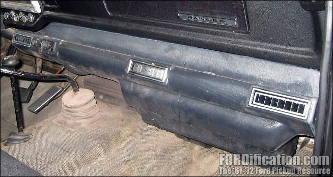
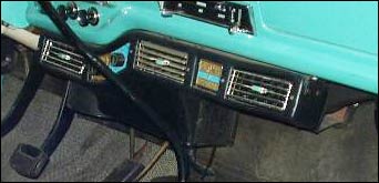
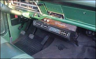
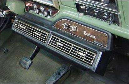
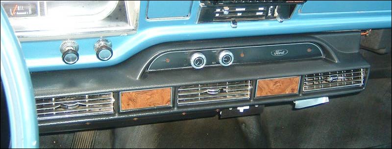
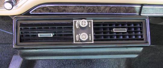
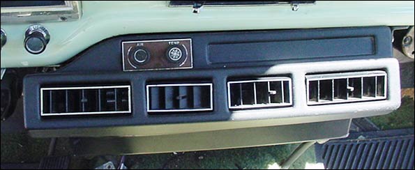
Although the factory A/C units were all dimensionally identical,
there was some minor changes in exterior trim. In the picture to
the right, you can see the '68-'69 style, the '70-only style and
the '71-'72 style. The '70 unit was a transition piece, which
used the '68-'69 register vents but the front aluminum valance
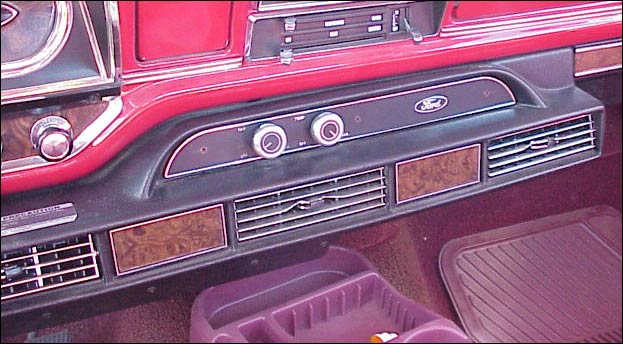
was upgraded with woodgrain trim. The '71-'72 units retained the
woodgrain but got restyled register vents. These trim pieces are
fully interchangeable between each other.
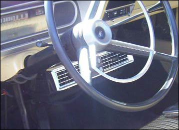
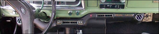
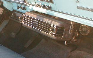
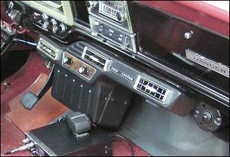
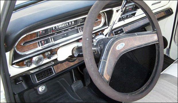
Here
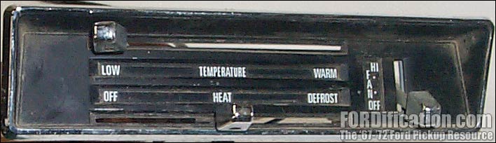
are the differences in the dash controls:
Fig. 4 - the standard '68-'72 heater controls |
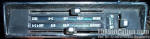
Fig. 5 - the '68-'72 factory A/C and heater
controls |
|

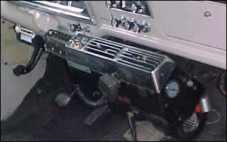
Fig. 1 - factory '68-'69 unit
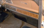
Fig. 2 - factory '71-'72 unit
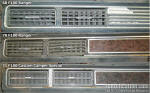
Fig. 3 - A comparison of the three trim styles |
|
As
mentioned above, the factory suitcase-style A/C unit replaces
the standard heater box, and comes with it's own set of dash
controls. To begin installation, you'll need to remove the
following items from your truck: |
- heater box assembly
- dash controls and cables
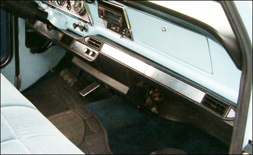
- glovebox insert - the glovebox insert will need to be
replaced with a much-shallower piece, since the A/C setup
extends upward into the glovebox area, taking up about half
of the available space (see Fig. 23).
- right-side fresh air vent
|
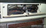
Fig. 23 |
|
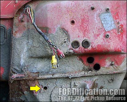
When
it comes time to mount the A/C box you'll have to trim away a
portion of your firewall cover, as shown in Fig. 24. The section
that needs to be removed should already be perforated as needed.
The yellow arrow points to a hole in the floorboard that will
need to be drilled for the evaporator drain. |
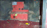
Fig. 24 |
|
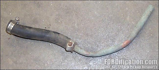
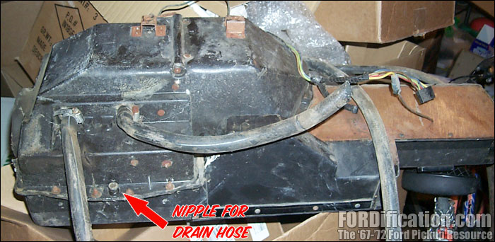
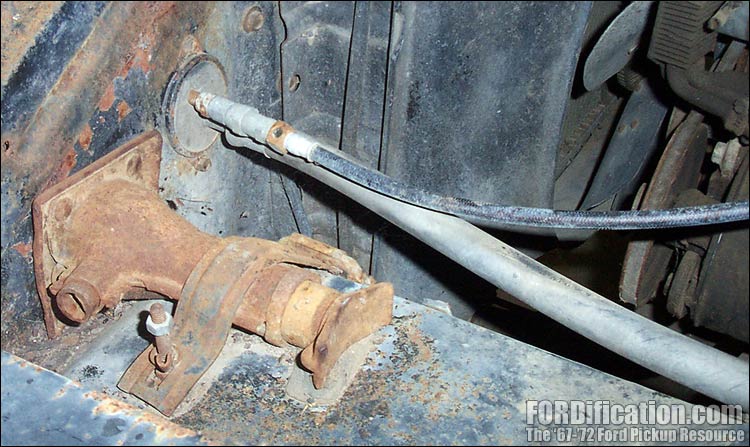
The
evaporator drain hose (Fig. 25) extends from the nipple on the
bottom of the unit (Fig. 26) down through the hole in Fig. 23
and then out through the right-front cab mount (yellow arrow in
Fig. 27).
|
|
Fig.
28 shows the piece that will replace the right-side fresh air
vent. The flexible duct between this and the A/C unit is
connected on both ends with a spring clamp. |
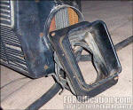
Fig. 28 |
|
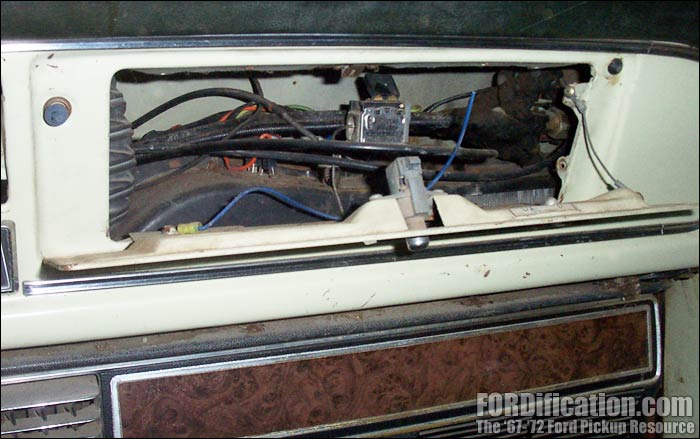
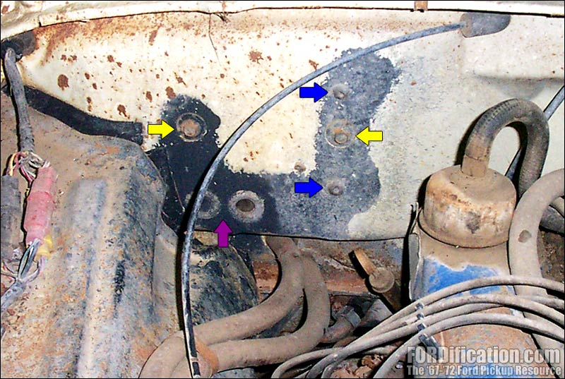
Figs.
29 thru 33 show a '70 Ranger with a factory-installed
A/C. In Fig. 29, the yellow arrows point to the two firewall mounting points of the
suitcase unit. The one on the left (as you're viewing the
picture) is one of the three holes already used with the
standard heater box which will also be used for the A/C unit.
The one on the right will need to be drilled. The blue arrows
point to the other two heater box bolt holes, which will need to
be closed off with body plugs, since they're no longer needed.
The purple arrow points to the plugs needed to fill the heater
core holes for the standard heater box. You will need to drill
two holes for the heater core hoses down lower (don't worry, the
firewall is already dimpled where you need to drill). |

Fig. 29 |
|
Fig.
30 shows where the A/C lines enter/exit the cab. There is a
rubber grommet here with three holes in it (one for each of the
lines and a smaller hole for the wire to the compressor's
clutch) and a metal retaining ring, held on with two screws. The
firewall will be dimpled where the two screw holes will need to
be drilled. |
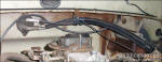
Fig. 30 |
|
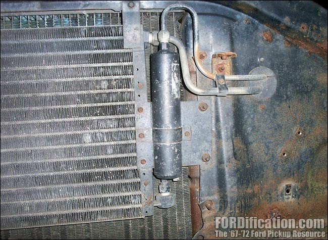
The
condenser and dryer are mounted on the front of the radiator
support. There is a grommet similar to the one pictured in Fig.
30 above for the lines, except that this one only has the two
holes for the lines. The condenser's mounting-bracket bolt holes should
already be drilled in the core support and be outfitted with
J-nuts. |
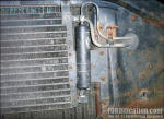
Fig. 31 |
|
A
view of the backside of the radiator support, showing the
grommet's retaining ring. The support is dimpled where the two
holes for the retaining ring's screws will need to be drilled. |

Fig. 32 |
|
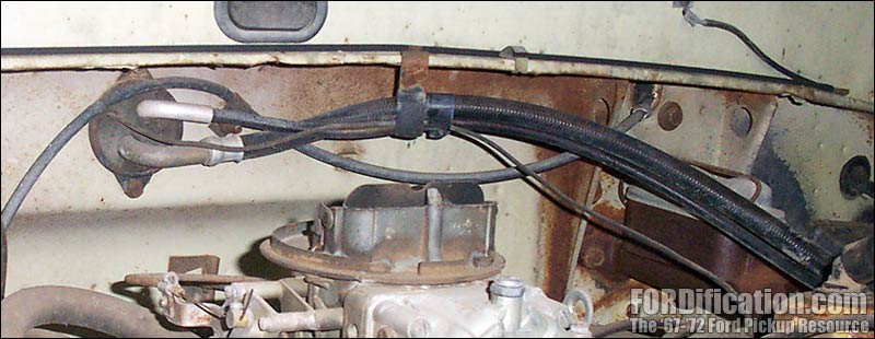
Here's a view of the underhood area, showing the compressor and
lines. The compressor has two braces...one which extends down to
a stud in the top of the driver's-side exhaust manifold, and
another which connects to the water pump area. Note that this
setup has the York compressor laying on it's side. However, the
factory also occasionally installed this on it's side and had
matching support braces. |
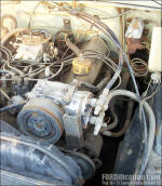
Fig. 33 |
NOTE: THIS TUTORIAL IS CURRENTLY UNDER CONSTRUCTION.
It will be updated in the near future with more detailed information
and better reference pictures as I complete the A/C installation on
my own truck.
|
|
 |

Want to link to
this site? Please save this banner to your hard drive to place on your
webpage.
The correct link to use is
http://www.fordification.com
|