FORDification.com
   (powered by Google)


  HOME

  Technical Articles

  Factory Literature

  Discussion Forums

  Photo Galleries


  Service Bulletins (TSBs)

  Decoding Your VIN

  Diagrams & Schematics

  Links & Resources

  In the Movies

  Downloads
  Member Meet & Greets

  In the Media

  Site Index

 MISC / PERSONAL

  My Truck Projects

  My Heinz 57 '67

  I've Been Censored!

  Contact


You are here: Home Tech Articles & Tutorials Steering / Suspension / Brakes Front Wheel Alignment Specifications
Back to Technical Index

Front Wheel Alignment Specifications


as printed in the August 1968 issue of Ford's 'Shop Tips' magazine

Truck Equipment Installation

Equipment used for front wheel alignment inspection must be accurate. If portable equipment is used, perform all inspection operations on a level floor.
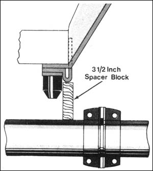
In checking wheel alignment of F-100, F-250 and F-350 (4 x 2) trucks, place a 4-inch spacer block between both frame side rails and I-beams (top right). A 3½-inch spacer block is used on F-100 (4 x 4) trucks between the side rails and front wheel drive axle (bottom right).

1. Drive the vehicle in a straight line to establish the straight-ahead position of the front wheels. Mark the steering column and steering hub with chalk to show the straight ahead position.

Do not adjust the steering wheel spoke position at this time.

If the front wheels are turned at any time during the inspection, align the chalk marks to bring the wheels back to the straight ahead position.

2. Install the wheel alignment equipment on the vehicle. Regardless of equipment used, be sure to follow the installation and inspection instructions provided by the equipment manufacturer.

Vehicle Model Front Axle Capacity Alignment Factors

CHECKING SPECIFICATIONS

Optimum Resetting Specifications Desired Alignment
Minimum Maximum Maximum Variation Between Wheels
F-100(1)
F-250(1)
2600
3000
Caster +3¼° +4¾° +4°
Camber +½° +1½° ⅝° +1°
Toe-in 1/16" 3/16" - ⅛"
King Pin Angle - - -
F-100
(4WD)
3000
3500
Caster(2) +2¾° +4¼° ½° 3½°
Camber(2) ½° 1½°
Toe-in 1/16" ¼" - ⅛"
King Pin Angle - - - 8½°
F-250 (4WD) 3000
3500
Caster +3½° +4½° ½° 1½°
Camber ½° 1½°
Toe-in 1/16" 3/16" - ⅛"
King Pin Angle - - - 7½°
F-350(3) 3800 Caster +4¼° +5¾°
Camber ⅝° +½°
Toe-in 1/16" 3/16" - ⅛"
King Pin Angle - - -

(1) Manual or Power Steering
The caster specifications shown are with the frame level from front to rear. Measure front to rear frame angle when checking alignment and compensate as follows: If the front of the frame is lower than the rear, the actual caster angle is obtained by adding the frame angle to the caster angle as shown on the checking equipment. If the front of the frame is higher than the rest, subtract the frame angle from the caster angle shown on the checking equipment.

The following instructions are to be followed to assure a correct camber reading on F-100 thru 350 Twin-I-Beam truck models:

Install a spacer block between each frame side rail and its respective front axle I-beam to obtain the height shown in views A and B. Raise the frame or add weight to the front of the vehicle to make sure the side rails rest on the blocks.
The radius of both front tires must be equal within ⅛". Radius to be checked from center line of spindle to the ground.

(2) View B = 3½ inches

(3) View A - 4 inches

The following scans were taken from the 1967 factory shop manual, and show the proper tools and technique for cold-bending the I-beams to correct camber issues.


You are here: Home Tech Articles & Tutorials Steering / Suspension / Brakes Front Wheel Alignment Specifications


Want to link to this site? Please save this banner to your hard drive to place on your webpage.
The correct link to use is http://www.fordification.com


Copyright library© 1999-2019 FORDification.com unless otherwise noted. All rights reserved.
All brand names and product names used on this website are trade names, service marks or registered trademarks of their respective holders.  
No portion or content of this site may be reproduced or otherwise used without explicit permission.
To report problems or provide comments or suggestions, please click here.