The alternator on my truck has begun to make a screech that make me believe the bearings are starting to go. My though is if I have to replace it, I might as well go to the 3G for the better output at lower RPM, since I usually don’t drive fast or far. That will let the truck charge the battery at idle, so while it just sitting there, instead of needing a long run each time.
I’ve been looking at the PA performance alternator and conversion kit. It costs a bit, but supposedly is a straight bolt in, with no pulley swapping or junkyard crawling, all new and lifetime warrantied.
https://www.paperformance.com/95a-3g-alternator-1614e/
also has a wiring Kit, and a ready made powerline
https://www.paperformance.com/1g-3g-conversion-462802c/
The wiring Kit supposedly will allow the current in-dash “Ammeter” to work.
I have been doing a lot of reading on this upgrade and while I haven’t read everything online about it, I’ve looked at a lot. On of the best threads is below. This article below is mustang-centric, of course, but the wiring diagram seem to match what our trucks have. There seems to even have been the fusible link added the same year.
https://www.vintage-mustang.com/threads ... n.1158686/
When I read this I see the point made about the possibilities of a short burning the old wiring, but I think that could be dealt with by putting a fusible link on that line, so now you have a fuse in the power line, and one on each end of the old wiring.
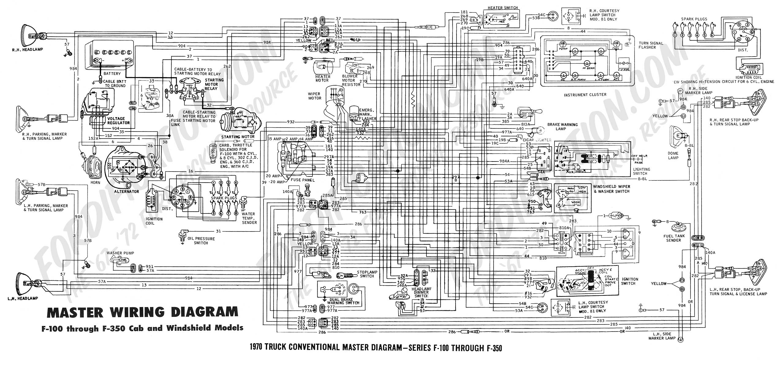
What I don’t understand is how much value there is in the old wiring. From the below, it looks like all of it could be removed, as all the regulator wiring seems almost a separate unit. It seems like as long as wire 37 and the new powerline are on the solenoid battery side, and somehow connect the wire from the “I” terminal to the 904 wire, it should trigger the field to excite work.
http://www.fordification.com/tech/wirin ... master.jpg
But in that set-up, does the “Ammeter” provide enough resistance to make the alternator excite?
I want to do this once and right, and the more I read the more I question.
If possible can the group help me understand the best option.
3G conversion: Please help me Understand.
Moderators: FORDification, Thunderfoot
-
TLXregnar07
- New Member

- Posts: 33
- Joined: Fri May 18, 2012 11:24 am
- Location: Northwest Georgia
-
cep62
- 100% FORDified!

- Posts: 2039
- Joined: Sun Oct 26, 2008 8:06 pm
- Location: West Michigan
Re: 3G conversion: Please help me Understand.
Not being a smart ass , but the screech might be a slipping belt ?
It might be worth a look.
It might be worth a look.
-
TLXregnar07
- New Member
- Posts: 33
- Joined: Fri May 18, 2012 11:24 am
- Location: Northwest Georgia
Re: 3G conversion: Please help me Understand.
The sound is more of a grinding. I can hear it louder when I use a stick as a primitive stethoscope.Fairly sure its the bearings.
But even so, I want to completely understand the 3G option. I know that the better charging at low RPM is worth it. Based on the chart of output versus RPM I found, and my tendency toward short low RPM trips, 3G should be the best choice.
But even so, I want to completely understand the 3G option. I know that the better charging at low RPM is worth it. Based on the chart of output versus RPM I found, and my tendency toward short low RPM trips, 3G should be the best choice.