Stepside to Styleside + Coyote & 10R80 with a Little Boost

Post progress reports on your project truck(s)

Moderator: FORDification

Post Reply
Aerocoupe
New Member
New Member
Posts: 119
Joined: Wed Aug 12, 2015 3:02 pm
Location: Jenks, OK

Stepside to Styleside + Coyote & 10R80 with a Little Boost

Post by Aerocoupe »

So I bought this truck just about four years ago and I knew this was going to be a long project with my family and work commitments. I've got it to the point now where its just cubic dollars so probably another three years but it will give me time to work on the small details. If we bite the bullet and build a house in the next two years then it may push out a little more but that will only be because I am going to be the general contractor and it will take up all the free time I have to manage that and my projects at work.

So here is the truck on the trailer coming back from Austin, TX.

Image

I did find a picture of the truck with the better of the two short boxes on it before we cut them up to make one.

Image

I got it cheap and even better was there was no motor or trans to have to remove and then haul off. The only thing I dd not like was the step side bed but I thought surely I could come up with one and possibly sell the step side. If anyone needs a step side bed let me know...ha ha ha!!! Damn thing is still in the conex taking up room. So I bought one bed from a guy in northern Arkansas knowing the bed was rough for $200. A few months later a second bed was purchased from a guy near central Arkansas in a lot better shape for $400. After media blasting both it was apparent that it was going o take a complete floor plus the two beds I had to make one good one. With that I decided to go ahead and order a new set of stock wheel wells and then split them in half. Using the center section from the best two original ones I had the bed was tubbed. Here are the pics of the bed being reconstructed using the floor out of a mid 80's long bed that was smashed on one side.

Sides from one bed, front from another, and bottom from yet another bed:
Image

Image

Then the wheel wells were welded up and installed along with the corner pieces of the bed floor in front and back of the wheel wells which were hand fabricated:
Image

Image

Image

Image

Took it from the metal fabricator over to my buddy's paint shop and they undercoated it and primed it. Couple shots of it unloaded and then on the truck:
Image

Image

So from here it was doing a lot of research on here and other sites, You Tube, Google searches, and figuring out what I wanted to do other than my usual make it fast and handle. Its the first truck I have built so I wasn't sure that fast and handle were possible but then I saw Sean's (Hackster's) LS build and got inspired minus the bowtie. So just so we are all on the same page here I am a Ford guy and my two garage queens are Fords and Ford powered and are low, fast, brake hard, and handle so this one will be low, fast, brake hard, and handle. Pics of my other two blue ovals:

The '83 T-Bird
Image

The '93 Coupe
Image
Last edited by Aerocoupe on Tue Nov 16, 2021 3:11 pm, edited 2 times in total.
Aerocoupe
New Member
New Member
Posts: 119
Joined: Wed Aug 12, 2015 3:02 pm
Location: Jenks, OK

Re: Stepside to Styleside + Coyote & 10R80 with a Little Boost

Post by Aerocoupe »

I looked at all kinds of suspensions all the way up to the wallet choking full blown tube chassis. My dislike of the tube chassis is that well one they are really expensive and two kinda boring when building something to just throw a chassis under it and move on. I completely get it as there no comparison with one of them even to a fully boxed stock frame but it seemed most everyone else was fine with the 40+ year old chassis with some smart modifications. So with that I decided to keep the stock frame and completely strip off all the stock suspension and just about every cross member. Holy crap I hate rivets now and have a lot of respect for how well they fasten things together.

For the suspension I looked at the Mustang II setups but hated the front spindles as they remind me of the Fox Mustang, Bird, and Cougar super horrible super crappy brakes. Both of my Foxes have the SN95 Mustang brakes upgraded to the Cobra setups which are light years ahead of the Mustang II design. I found several folks talking about the Crown Vic front suspension and the more I looked into it the better it sounded. I purchased a 2007 CV PI front suspension and after tearing it down the only thing I ended up keeping was the engine cross member, lower control arms, the upper brackets that attach it to the frame, salvaged the spacer tubes from the sections of the cars frame that came with it, the rack and pinion, and all the bolting. With my searches on this setup I came across a Mercury Marauder site with a couple of guys making an adapter for the Mustang GT500 14" rotors and the Corvette C5 calipers. I bought the adapters and the custom SS brake lines from another vendor on the site. Continuing my research I came across Naake and bought their front coil over kit for the Mercury Marauder. Now I was down to pieces parts like the C5 calipers, GT500 rotors, reman rack and pinion, outer tie rods, sway bar end links, complete FoMoCo UCA's, LCA forward bushing, LCA rear bushing/bracket, LCA ball joint, SPC/ADTR camber kit, and ADTR's front sway bar with urethane frame mounts.

This over a year of researching and buying parts so then it was time to put it together. I ended up stripping the cross member by scrubbing it with Dawn dish washing liquid, three applications of Eagle 1 mag cleaner with lots of scrubbing, and then once again washing it with Dawn.

What I started with
Image

Cleaned up
Image

I then mocked up the relocation brackets for the Coyote motor so it is located in the truck correctly. I got these from Outcast Autoworks and they are quality pieces. I will also be using their motor mounts as they allow more clearance for headers and steering linkage than the stock motor mounts.

Image

So from here I took it to the powder coaters to get clear coated. I also took the wheel knuckles, LCA's, upper coil over mounts, and upper CV cross member braces to get coated black. I chased the threads on all of the bolting then had it media blasted and then zinc coated clear for about a fifth of buying all of it new and the coating looks better and is more durable than the factory coating.

Image

Image

From here it will be assembly and installing it in the truck but that is later down the line. Its late so I will pick back up here tomorrow.
Last edited by Aerocoupe on Tue Nov 16, 2021 3:12 pm, edited 1 time in total.
Aerocoupe
New Member
New Member
Posts: 119
Joined: Wed Aug 12, 2015 3:02 pm
Location: Jenks, OK

Re: Stepside to Styleside + Coyote & 10R80 with a Little Boost

Post by Aerocoupe »

The process of stripping all the suspension and cross members off the stock frame that I would not be needing was more of a chore than I expected. This was due to not being able to punch out the rivets anywhere they passed through two pieces of metal. After you get the hang of it then its not bad but still time consuming. So I started with the rear suspension and did not take a before picture but I am pretty sure those here know what it looks like factory. Here are some shots of the work from the factory suspension to the bare frame with the exception of the brace we welded in.

Removing the rear end, springs, shocks, etc.
Image

Image

Had to clean up as I was loosing track of tools:
Image

Frame stripped of all the suspension parts and brackets:
Image

Rear frame completely stripped with the Z brace welded in:
Image

Image

Image

So I moved on to the front suspension and started in on that by removing all the twin I-beam related parts and steering. Then I got into removing the spring horns and all the other brackets and got it down to the engine cross member.

I-Beam removal:
Image

Image

Image

The next step was removing the spring horns, radius arm rear mounts and the cross member between the engine cross member and the transmission cross member which will be replaced with a welded in tubular piece once the engine, transmission and exhaust placement is figured out:

Image

Image

Image

Then it was time to cut out the engine cross member so the front clip was removed and put up in storage. I saw a guy use a circular saw with a metal cutting blade in it to cut the top side of the cross member and then he had very little work to do with a sawzall. This was the approach I took and it was super easy but you just have to let the metal blade cut at its own speed and not put much pressure on it.

Image

Here are the two top cuts:
Image

Image

We welded the Z braces in after using the skill saw to make the top cuts. Turned out we could have welded them in before and not been in the way. So this picture is with the engine cross member removed as well as the power steering gear box attachment point.

Image
Last edited by Aerocoupe on Tue Nov 16, 2021 3:12 pm, edited 1 time in total.
Aerocoupe
New Member
New Member
Posts: 119
Joined: Wed Aug 12, 2015 3:02 pm
Location: Jenks, OK

Re: Stepside to Styleside + Coyote & 10R80 with a Little Boost

Post by Aerocoupe »

I saw where some just started welding in the boxing material without removing the remaining parts of the engine cross member in the frame cross sectional area and some went to the trouble of removing it. I decided to remove it just because it serves no purpose and would most likely get in the way of welding out the tube spacers. With some cutting and working these metal pieced back and fourth on the welds I was able to break them out in three pieces on each side. Used the 4" grinder and cleaned it up so everything turned out pretty nice.

Passenger side
Image

Image

Driver side
Image

Image

So I now had the frame completely stripped and ready to start putting in the Crown Vic front suspension and the Fatman Fabrications parallel four link. I started with the front as my buddy that does all the welding was on his hitch with Haliburton for a couple weeks. Laying out the location to drill the holes for the tube spacers was again based on research and watching Texas Know How on your tube. That guy is pretty good at detailing his stuff. I also watched another guy on You Tube and read some of the installs on different forums. What I came up with is if you do not want to move the centerline of the front wheels then this is the approximate dimensions as to where the holes go for the locating pins on the CV cross member.

Locating pins on the cross member
Image

Location on frame (same on both sides)
Image

I center punched the locating pin holes first and then used a 1/8" drill bit to pilot them. From there I calipered just below the taper on the pins to determine the hole size. I decided that the forward hole needed to be welded up as the step drill bit was going to get into it and that is no bueno. Once these get drilled then the cross member can be put under the frame and the holes for the bolts that pass through the truck frame can be located on the bottom of the frame. Remove the cross member and then transfer the locations to the top of the frame. Again, I center punched all of this first and then used a 1/8" drill bit to pilot all four holes. The bottom holes will need to be big enough to pass the bolts through them and the top holes will need to be big enough to pass the spacer tubes through them. Again I calipered the bolting and the tubes. I do not remember the bolting diameter but I do remember that the hole size for the tubes was 1-5/16" and the step bit I had only went to 7/8" so I bought the next size up that wend to 1-3/8". Again it was determined that there was a factory hole in the top of the frame that needed to be welded up for the rear spacer tube hole on both side. After all this you get this:

Image

Image

So after this I slide the cross member back under the truck and bolted it down to 100 ft-lbs (spec is 184 but its coming back out once the tubes are tack welded) and put the suspension together.

Cross member with the UCA's installed:
Image

Image

Completed front suspension:
Image

Installed the upper frame brackets:
Image

Image

Image
Last edited by Aerocoupe on Tue Nov 16, 2021 3:13 pm, edited 1 time in total.
Aerocoupe
New Member
New Member
Posts: 119
Joined: Wed Aug 12, 2015 3:02 pm
Location: Jenks, OK

Re: Stepside to Styleside + Coyote & 10R80 with a Little Boost

Post by Aerocoupe »

From here it needed to go to my buddy's shop to get the four link installed (his tig and mig welder are there and its inside so the shielding gas doesn't bet blown all over the place). I installed the old wheels off my 93 Coupe on the front so that would roll.

Cobra wheels installed and front end on the ground and the rear of the truck is not leveled to the front:
Image

Image

So now the rear end needed to be mobile as I had removed the rear end and stripped it down to just the housing and cut the ends cut off (more on this later). In comes the getto rear axle...it went up on the trailer and back down and into his shop so I was relieved and also happy the scrap I found around the shop worked. We did put the rear of the truck on jack stands for the trailer ride over to his shop (15 miles) and cross strapped and then ran two more straps straight across the frame to ensure it was tied down.

Getto axle:
Image

So from here its about the four link install which neither of us had ever done but we had a common friend that builds race cars that was our lifeline in case we had questions.
Last edited by Aerocoupe on Tue Nov 16, 2021 3:13 pm, edited 1 time in total.
User avatar
Bullitt74
Preferred User
Preferred User
Posts: 430
Joined: Thu Sep 22, 2016 5:34 pm
Location: Red Deer, Alberta, Canada

Re: Stepside to Styleside + Coyote & 6R80 with a Little Boost

Post by Bullitt74 »

Wow, very cool build so far! I’ll be following! :pop:
Steve F.
Red Deer, Alberta, Canada
'72 Ranger XLT, 4x2, 390-2V, C6, Wind blue & Wimbledon White (‘Smokey’)
8)
2016 F150 Lariat FX4 Supercrew, Ruby Red
Follow my build thread for 'Smokey': http://fordification.com/forum/viewtopi ... 22&t=85070
User avatar
DuckRyder
Moderator
Moderator
Posts: 4893
Joined: Mon Jul 19, 2004 3:04 pm
Location: Scruffy City
Contact:

Re: Stepside to Styleside + Coyote & 6R80 with a Little Boost

Post by DuckRyder »

I’m liking it so far, nice pictures... :thup:
Robert
1972 F100 Ranger XLT (445/C6/9” 3.50 Truetrac)

"An unarmed man can only flee from evil, and evil is not overcome by fleeing from it." -- Jeff Cooper
Aerocoupe
New Member
New Member
Posts: 119
Joined: Wed Aug 12, 2015 3:02 pm
Location: Jenks, OK

Re: Stepside to Styleside + Coyote & 10R80 with a Little Boost

Post by Aerocoupe »

Appreciate it. My guess is I am another couple years from finishing as the drive train, wheels & tires, and paint are gonna be big hits that I cannot buy parts, horde them, and then binge install. I am gonna have to save money and bite some big tickets to make the purchases. The turbo system I can buy here and there and the dollar hits won't be horrible but buying the Coyote, 6R80, and all the electronics is a one stop shop. My buddy owns a paint shop but he knows me and I am not going to settle for a car lot special paint job so that will be several thousand. Will be Line-Xing the interior of the bed so that will be the cheapest thing but that is last. The interior should not be too bad but even getting a couple bucket seats upholstered now is not cheap. When you see what I have planned for the rear wheels and tires you will understand the dollar layout there as well. Anyone interested in buying a '93 Coupe with a 331 and full Maximum Motorsports suspension? Kidding, will never get one back like it so no selling of the toys to build a toy.

Anyhow, back to the build. So I wanted to tie some things together as I have posted a couple threads on here about a variety of things. I think this is a good time to bring all of that into this build thread so that if anyone is looking for the info it is all here or at least I hope I have captured it all.

So one of the first things I started to go over was rebuilding the Crown Vic IFS as I am not one to put a XX,XXX mile used front suspension under a truck like this. I don't want the headaches down the road and who knows how it was abused before I got it being it was a police interceptor car. So this suspension came with steel LCA's, then aluminum, and then back to steel. I am not sure why Ford did this but I am not a fan of the aluminum LCA's for my own reasons (seems to be hot topic of debate). It also seems that aluminum LCA's are the ones that you can buy at the parts stores and online at the best price but they do offer the FoMoCo steel units at around $270 each. The PI front suspension I got came with the steel LCA's as I requested them to be steel. My thought was I could replace the ball joint and forward bushing and powder coated the control arm for much cheaper than a new one. After three months of searching (in my spare time) I finally found the part number for the forward bushing. Not one parts store sells them but somehow or another all the complete control arms they sold had them. Here is the thread on that so I am not regurgitating the same info twice. I will admit that I hosed it and did not direct the machine shop on which direction to press the ball joints in and they guessed the wrong way so I paid for that twice...lesson learned the hard way.

http://www.fordification.com/forum/view ... =5&t=88579

Next up was how the heck was I going to get the 5.0L Coyote to mount up to a cross member that was made for a 4.6L mod motor? After some research there it is common knowledge that the 4.6, 5.4, and 5.0 will all bolt up to this cross member with the 4.6L Crown Vic motor mounts. Granted you have to use an aftermarket oil pan on the Coyote motor but it will work. I did more digging and found Outcast Autoworks makes an adapter to move the Coyote back which helps with clearance and the now make motor mounts that have all kinds of adjustability so I will be getting those as well. Again, another thread I started on this topic so no need to go any further on it here.

http://www.fordification.com/forum/view ... =5&t=87643

I am going to see if I can keep the stock oil pan which if I can would just about be a break even being the parts from Outcast are about the same price.

Another issue is the EVO system on the rack and pinions. For those that do not know this system controls the boost on the rack in relation to speed. From what I have read the EVO allows full boost from 0 mph up to 40 mph. After 40 mph the computer uses wheel speed to start closing the solenoid valve which reduces the amount of pressure or "boost" to the rack. This increases road feel and stability of the car at high speeds. If you leave it wide open the steering will be very touchy at higher speeds. I went thought all kinds of BS trying to find a rack without this feature. They do offer racks without the EVO but what that means is you remove it from your old rack and install it on your new one. I gave up and bought a complete one as some had reported not being able to get their old one off. I will be using DC motor controller to adjust the EVO solenoid valve to an optimum opening amount. It would be nice if someone made a mechanical orifice to put in place of the EVO solenoid but I have not found one to date. This is the controller I will use as several others have used it and report it is working really well and has been of for one guy for over two years.

https://www.amazon.com/gp/product/B00RY ... UTF8&psc=1

The next thing on the list was bigger brakes as this truck is gonna need some stopping power. Basically I am using an adapter that allows the use of the 14" Mustang GT 500 front rotors and a C5 Vette caliper and I opted for some custom SS brake lines. All of that is here:

http://www.fordification.com/forum/view ... =5&t=83166

I previously mentioned I salvaged the tube spacers from the sections of the Crown Vic frame that came with my IFS. Here is the thread on that

http://www.fordification.com/forum/view ... =5&t=87923

The last thing I wanted to tie into this build thread was the torque specs for the Crown Vic front end which is here:

http://www.fordification.com/forum/view ... =5&t=88608

I will get the four link install posted up next but I am off today and my F150 needs new brake pads installed which most likely means turning the rotors as well. So 30 minutes of tear down and a couple hours waiting on rotors and 30 min to go back together will be my afternoon.
Last edited by Aerocoupe on Tue Nov 16, 2021 3:13 pm, edited 1 time in total.
Aerocoupe
New Member
New Member
Posts: 119
Joined: Wed Aug 12, 2015 3:02 pm
Location: Jenks, OK

Re: Stepside to Styleside + Coyote & 10R80 with a Little Boost

Post by Aerocoupe »

I looked at what people had done for a rear suspension on these trucks with them lowered and the vast majority were refurbishing the stock leaf spring setup and using lowering blocks. I saw where one guy disassembled the leaf spring packs and completely rebuilt them with new Teflon pads, new bushings in the eyelets, and media blasting each leaf and using POR15 on each one. Looked really good and other than the springs being worn out a cheap way to go about it. Some have stuck with the 9" and others have opted for the '01 and down Explorer rear end that came factory with leaf springs. Good option for gearing, traclok, and disc brakes with integral parking brake that can be hooked up to the e-brake pedal in our trucks. I saw where Hackster used an 8.8 out of a Coyote Mustang and fabbed up the brackets to utilize the three link which was pretty sweet. That guy is amazing and does it all.

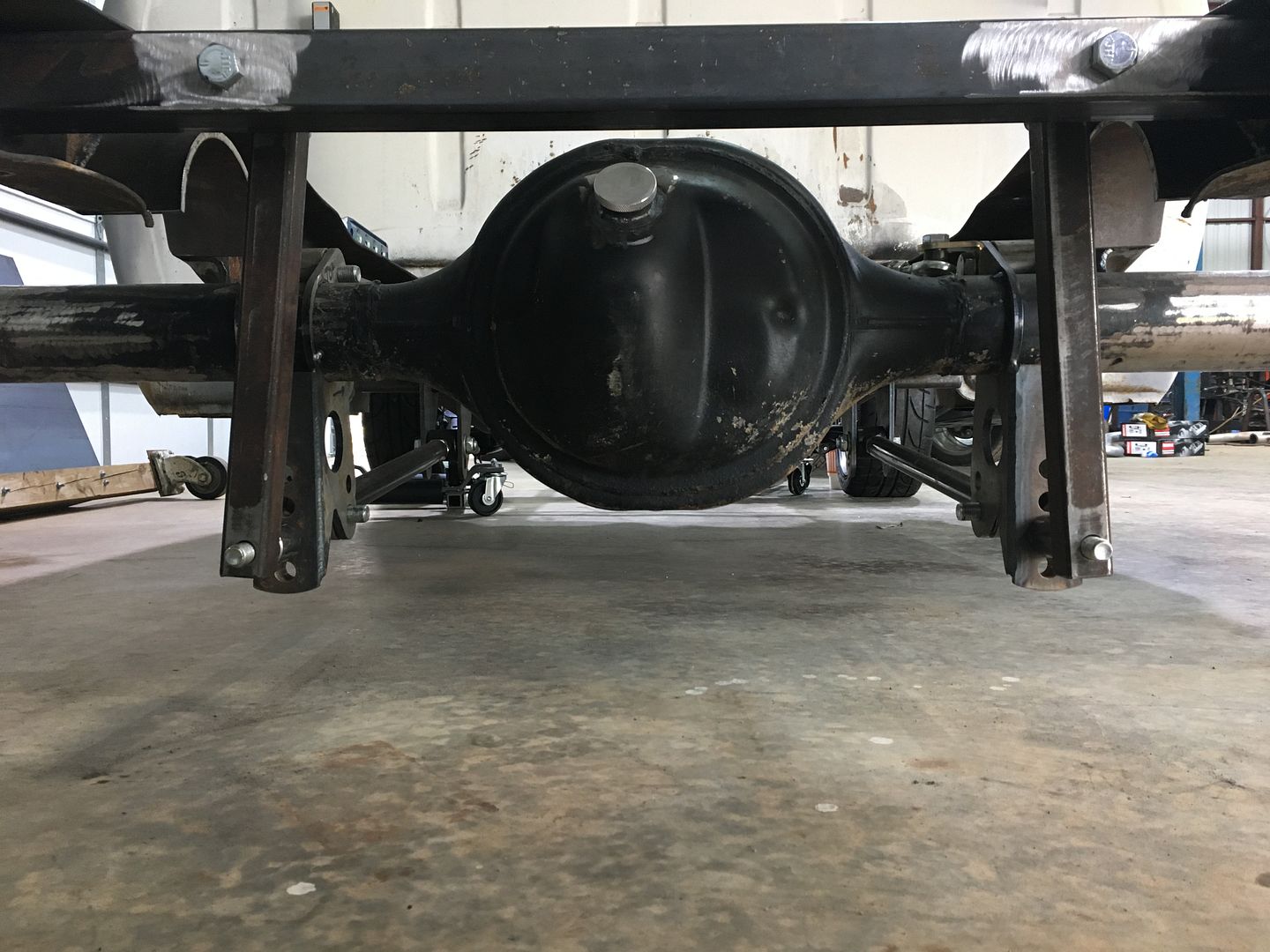
My thought was to use the existing 9" being it was free and we had several old nine inch parts laying around the shop from other projects. I ended up using a spare 3rd member and had it built with 3.73's, new traclok, and a complete builder kit of Timken seals and bearings. My original thought was to leave the rear end the stock length but after some research and talking to guys with tubbed vehicles it was obvious I was going to have to narrow the rear end. That sucked to find out as I had already ordered stock length Moser axles for the rear end. So now that it will be narrowed they will have to go back to Moser to get cut to length and resplined for an additional charge. So now that I had a better plan I had the same guy that set up the gears cut the ends off the housing being he will be the one welding them on and finishing the welds on the four link brackets. He has a jig and will tig weld all fo that. I removed the spring perches and shock mount brackets and then cleaned up the inside of the rear end. I do not think this rear end was ever serviced in its life. The gear oil was the consistency of bearing grease and there was more in the axle tubes that had to be scraped out.

This is what came out of the rear end
Image

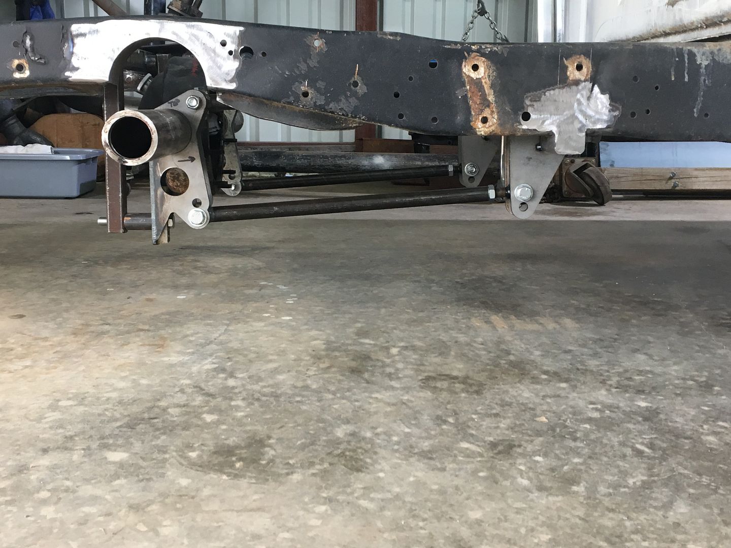
So I spent a full day getting the truck level from front to back and side to side to start the process of installing the four link. I laid out the suspension pieces and then started measuring and measuring and measuring some more. I put the rear end under it and the driveshaft loop cross member that the front four link brackets will attach to. I had to open up the ID of the four link rear brackets that slide on the axle tube as they were 3.00" and the stock axle tubes are 3.09". Metal carbide bit, die grinder, and a few minutes took care of that issue.

Image

If it appears that the drive shaft loop cross member is offset to the passenger side you are correct. The 9" is centered in the truck and the center line of the pinion on it is 15/16" to the passenger side so we moved the loop over 1" to the passenger side. The motor and trans have a factory offset of 3/4" to the passenger side and with the motor mounts I am getting I can correct that to 1". Hopefully I can get a straight shot left to right on the drive shaft so the u-joints are only dealing with the up and down.

So with this setup the top of the drive shaft loop cross member is level with the center line of the rear axle. You need to know the diameter of the tire you are going to run to set this up and also know the ride height of the vehicle. From there the back of the drive shaft loop cross member is 25-3/4" forward of the rear axle center line. Once you have all of this figured out then its level the frame up from front to back and side to side and fire the plasma cutter up. We started with the driver shaft loop cross member first:

Plasma cutter in action
Image

Fitment of cross member
Image

Image

Image

Welded it up and then a couple rounds of welding to fill in the gaps and lots of grinding got this
Image

We will add a couple of gussets on the inside of the frame once it is boxed and weld the boxing to the cross member so it should be plenty stout.

From here we moved to the 3" c-notches as the ride height will have the top of the axle tubes 1" from the bottom of the frame and the travel on the suspension is +/- 3". With the notches I have 4" above the axle tube and the top of the rear end will miss the bottom of the bed by 1/4" so bump stops will be mandatory.

Metal prepped and c-notch marked (notice the long dimple on the left there is one on the right as well)
Image

Plasma cutter back in action (you can see the c-notch on top of the frame to the left)
Image

Welding in the c-notch (6.625" x 0.280" pipe that was cut 3-1/4" wide and then split in half all on a band saw)
Image

Back of the c-notch installed
Image

The bottom of the frame in front and back of the c-notch will be cut out as Ford clearanced the frame for the shocks. This was done in a press when the frame was made and we did debate heating it up and just hammering it flat and then thought better of it. Plasma cutter will make short work of it and I will make some templates and transfer those shapes to some plate I bought for this and the boxing work. Should look pretty slick when it is done. I am debating on getting a dimple die set and putting holes in the boxing plate. This would be for looks but also media blasting and getting the powder coat all in there.

Front side with additional welding to fill in some factory dimples
Image

Ground all of that flat and then added some more filler weld and ground that down and then hit it with some 80 grit on a flapper wheel
Image

So this is where we left it after two days of lots of interruptions which included attending two BBq's
Image
Last edited by Aerocoupe on Tue Nov 16, 2021 3:13 pm, edited 3 times in total.
Aerocoupe
New Member
New Member
Posts: 119
Joined: Wed Aug 12, 2015 3:02 pm
Location: Jenks, OK

Re: Stepside to Styleside + Coyote & 10R80 with a Little Boost

Post by Aerocoupe »

So the next morning (took the day off) I went back out to my buddy's shop and we installed the bar between the frame rails for the upper coil over mount and the Z-bar. I didn't take a lot of pictures of the fitment as there was weather moving in and I wanted to be back home before all that crap hit there. The bar had to be cut to length and then two 3" heavy wall pipe spacers installed such that only 1" stuck out from the bar. We used the drill press and a hole saw to make that happen and my buddy tigged up the side that stuck out and then mig welded the back side and ground that flat. The top of the coil overs are 1" inboard relative to the lower mount so we had to account for that as well which is where the plumb bob came in handy...again.

Upper coil over mount getting welded in
Image

And the four link is in all be it with the dummy bars in place of the coil overs. We did this so things would not move around while it got welded up and who wants to weld around that stuff anyhow. I worked myself up over this damn install and after it was all said and done my buddy and I looked it over and then he said "We could do this in one day now". I would say two but all he did was weld and make four cuts with the plasma and I did all the measuring, calcs, metal prep, and yeah holy **** this was pretty easy.

The welds on the forward brackets need to be done as well as a couple welds on the coil over bar but that is it. The brackets on the rear end are tack welded but it will come back out and go into a jig and get about 4" cut off one side and 6" off the other and the new ends put on with some pretty tig welds. Here are a few shots of all of it in place, I'm liking it...

Image

Image

Image

Image

Image

Taking a week off here in a couple weeks and hopefully we can get the front suspension all welded up (spacer tubes, boxing, and the rear LCA mounts) and box the rear frame. Lots of trimming, templates, and welding but it should look pretty sweet when done. From there it will be put the bed on the truck and 100% figure out how much to narrow the rear end. Once that is narrowed then we will have the Moser axles shortened and resplined.

To get it rolling around new big bearing Torino ends will be welded to it. This will allow for the Explorer disc brake kit to be installed with the matching 4.5 x 5 bolt pattern as the CV stuff up front. Then the other two Cobra wheels will go on it and we will get it back over to my dad's shop. From here its pretty much at a stand still until I can come up with the funds to buy the motor and trans.
Last edited by Aerocoupe on Tue Nov 16, 2021 3:14 pm, edited 2 times in total.
miller
New Member
New Member
Posts: 144
Joined: Tue May 21, 2019 7:33 am

Re: Stepside to Styleside + Coyote & 6R80 with a Little Boost

Post by miller »

You and I are going down same path! Looking good and will help me out with the forest service truck.
IN2FORD
Preferred User
Preferred User
Posts: 345
Joined: Sun Apr 27, 2014 3:54 pm
Location: Cookeville TN

Re: Stepside to Styleside + Coyote & 6R80 with a Little Boost

Post by IN2FORD »

Love this build and Love the Foxes!! Had a bunch of foxbodies. Sold my 90 vert to build my truck.

Barry
"Krusty Kab"
Aerocoupe
New Member
New Member
Posts: 119
Joined: Wed Aug 12, 2015 3:02 pm
Location: Jenks, OK

Re: Stepside to Styleside + Coyote & 10R80 with a Little Boost

Post by Aerocoupe »

Got some more time last weekend to work on the truck. I got the bottom lip of the frame cut out in front and behind both "C" notches and made some templates to transfer the shapes onto the sheet of 10 gauge SA-36 steel. Got those cut out with the plasma torch, shaped them, and then burned them in.

Image

Image

Image

Image

Image

Image

Got the bottom side welded up and then ground all of that flat and brightened it up. Still a couple small spots to weld up so it is filled in but we will get those when we are done welding up the boxing plates.

Image

Image

From here I stared making the templates for the boxing plates on the rear of the truck and for the front as well. I was going to try and do the rear plate in one piece but getting it around the front support for the four link, the "C" notch, and the rear coil over upper support bar was going to be a pain so I opted to two piece it.

Here is the template for the back section of the rear boxing plate
Image

Then the rear boxing plate fitted with the front template being fitted
Image

Front and rear boxing plates fitted and ready to tack into place
Image

Moved to the front of the truck and made the templates to box the frame where the Crown Vic IFS is installed. Welded up the spacer tubes and then cut the boxing plate out and fitted both sides. I think we are going to heat the frame in a couple spots as the lips on the frame are just not 100% straight and it will make the welding a lot better.

Image

Image

Should get back on welding out the boxing plates this weekend if all goes well.
Last edited by Aerocoupe on Tue Nov 16, 2021 3:14 pm, edited 1 time in total.
RottenAppleRed
New Member
New Member
Posts: 83
Joined: Fri Apr 14, 2017 10:33 pm
Location: Anderson, Indiana

Re: Stepside to Styleside + Coyote & 6R80 with a Little Boost

Post by RottenAppleRed »

Really nice...ready for page 2 and beyond.
User avatar
hfdco4
Blue Oval Guru
Blue Oval Guru
Posts: 1289
Joined: Mon Apr 01, 2013 1:45 pm

Re: Stepside to Styleside + Coyote & 6R80 with a Little Boost

Post by hfdco4 »

Simply amazing work! I am in complete awe, based on your attention to detail so far this is going to be a show stopper!
:fr: :thup: :D :woohoo: :hd:
Paul
:fr: FE390PC
1970 F250 4x4
2016 F150 4x4 2.7 ECO
Gone 1997, 1999 & 2003 F150 4x4s
Gone 1988, 1989 & 1991 Broncs
Post Reply