Ammeter Wiring

Electrical and Wiring Forum Archives
Post Reply
User avatar
jor
Blue Oval Fan
Blue Oval Fan
Posts: 682
Joined: Fri Jul 23, 2004 9:28 am
Location: Arizona, Tucson

Ammeter Wiring

Post by jor »

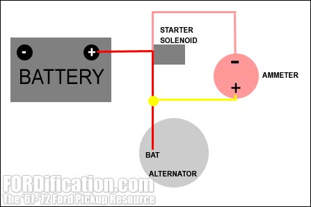
The red wire (A) coming from the discharge side of the ammeter goes through the wiring harness and hooks up to the hot side of the starter solenoid. The yellow wire (B) coming from the charge side of the ammeter goes through the wiring harness and ties into the 10 AWG cable which goes between the hot side of the starter solenoid and the alternator. The points at which the two wires connect to the solenoid-to-alternator cable are about 23-1/8" apart. However, this cable does not "meter" power to the ammeter...it has virtually no resistance. Using a sensitive ohmmeter, we were only able to detect about .10Ω resistance between the point where it begins at the starter solenoid and where the shunt, or power diversion, is connected. Therefore, it appears that even though the yellow wire is connected in the middle of the solenoid-to-alternator cable, where the factory spliced it in, it would be just as effective to hook it up at the alternator itself at the FLD connection where the cable itself is attached.


This quote is from Keith's research on the factory ammeter wiring. My harness is a bit jury rigged and I'd like to get my factory (actually an F-600 set) ammeter working. If I understand this correctly, it seems pretty easy.I guess I can just run a wire from the ammeter to the starter side of the starter solenoid and another from the ammeter to the #10 wire that runs from the solenoid to the alternator (or directly to the Field on the alternator). Can it really be this easy?
jor
User avatar
68F250
Blue Oval Guru
Blue Oval Guru
Posts: 1174
Joined: Thu Jul 22, 2004 3:26 pm
Location: California, Brea

re: Ammeter Wiring

Post by 68F250 »

Where did you get that quote?

There should be no connection to the field, it's on a different circuit.

The only thing that attaches to the starter side of the solenoid is the starter itself.

There's an attachment in a recent thread on the ammeter, it shows the wiring diagram for the ammeter. Look at it for a while and you'll see why the ammeter wires are attached where they're at. It's so it can sense the current direction and magnitude.
Barry

"Are you gonna make it all 220?"
"Yeah 220, 221, whatever it takes."
User avatar
jor
Blue Oval Fan
Blue Oval Fan
Posts: 682
Joined: Fri Jul 23, 2004 9:28 am
Location: Arizona, Tucson

re: Ammeter Wiring

Post by jor »

User avatar
FORDification
Site & Forum Admin
Site & Forum Admin
Posts: 8047
Joined: Sun Jul 11, 2004 12:52 am
Location: Kansas, Wellsville
Contact:

re: Ammeter Wiring

Post by FORDification »

Barry's right, while some of the info on that page isn't 100% complete since I'm still researching it, I CAN say that the ammeter connections do not go to the alternator's Field terminal. They connect as shown in this graphic, also displayed on the page linked to above:

Image

You'd have to connect the lead to the battery side of the solenoid, not the starter side. And while I did post on that page that the cable between the battery and alternator doesn't appear to be resisted, it's entirely possible that it is, but to such a small degree that my ohmmeter couldn't pick it up. It's because of this that I have to tentatively agree that you could hook up a factory ammeter by attaching the positive lead to BAT terminal of the alternator and the negative lead to the battery side of the starter solenoid. However, since I haven't gotten this far on my project yet, I haven't tried it to see if it would work. It's just my theory.
Last edited by FORDification on Fri Aug 05, 2005 4:43 pm, edited 1 time in total.
____| \__
-O-----O- Keith
'67 F-100 2WD SWB ~ '69 F-100 4WD SWB w/7" chop ~ 1975 F-250 Ranger XLT Supercab Camper Special
ImageImageImage
My '67 restoration video
-> Posting and you! <-a MUST watch for all!!
User avatar
68F250
Blue Oval Guru
Blue Oval Guru
Posts: 1174
Joined: Thu Jul 22, 2004 3:26 pm
Location: California, Brea

re: Ammeter Wiring

Post by 68F250 »

Thanks Keith! That's what I think is happening too. The ammeter is measuring the voltage drop of the cable itself. An ohmmeter can't measure the resistance 'cause it's too small but start pumping a lot of current thru it and there will be a small voltage drop.

Jor, I would try out what Keith has suggested. I've always wanted to test that theory but never got around to it. Hook one end of the ammeter to the battery side of the starter solenoid and hook the other end of the ammeter to the 'BAT' terminal of the alternator.

Also, I hope my posts aren't coming off as harsh, it's hard to read the inflection in the written word. :)

Good luck! Don't let the smoke out. :eek:
Barry

"Are you gonna make it all 220?"
"Yeah 220, 221, whatever it takes."
User avatar
jor
Blue Oval Fan
Blue Oval Fan
Posts: 682
Joined: Fri Jul 23, 2004 9:28 am
Location: Arizona, Tucson

re: Ammeter Wiring

Post by jor »

Thanks, guys. I'd hate to make a mistake on this and end up with a fried loom! Not harsh at all; I appreciate the advice.
jor
User avatar
68F250
Blue Oval Guru
Blue Oval Guru
Posts: 1174
Joined: Thu Jul 22, 2004 3:26 pm
Location: California, Brea

re: Ammeter Wiring

Post by 68F250 »

Great! Sometimes when I read back my own posts they seem harsh.

Anyway, I wouldn't worry about frying anything. There was an article at a Mustang site that showed how to hook up the stock ammeter in an early Mustang that had idiot lights. They showed what we are talking about, one end to the alternator and the other end to the solenoid. Now keep in mind that this conversion kept the existing alternator harness. That's why I think it's only measuring the voltage drop of the cable.
Barry

"Are you gonna make it all 220?"
"Yeah 220, 221, whatever it takes."
User avatar
bluef250
Blue Oval Fanatic
Blue Oval Fanatic
Posts: 924
Joined: Fri Oct 29, 2004 8:49 pm
Location: Arizona

re: Ammeter Wiring

Post by bluef250 »

I would suggest you install 4 amp fuses in line between connections and the gauge on both wires when you make connections to the alternator and to the battery side of the starter solenoid. That way the fuses will burn not the gauge if you have a problem. The stock wiring on the 68 has 4 amp fuses at the starter solenoid and after the splice from the alternator. Let us know how much movement the gauge has.
User avatar
FORDification
Site & Forum Admin
Site & Forum Admin
Posts: 8047
Joined: Sun Jul 11, 2004 12:52 am
Location: Kansas, Wellsville
Contact:

re: Ammeter Wiring

Post by FORDification »

Good point....the '67s didn't have fuses, from what I understand, but the '68-up did. I'll be adding them to mine.
____| \__
-O-----O- Keith
'67 F-100 2WD SWB ~ '69 F-100 4WD SWB w/7" chop ~ 1975 F-250 Ranger XLT Supercab Camper Special
ImageImageImage
My '67 restoration video
-> Posting and you! <-a MUST watch for all!!
Post Reply