Steel Clydesdale wrote:Thanks for all your replies and suggestions--Great shop tips!
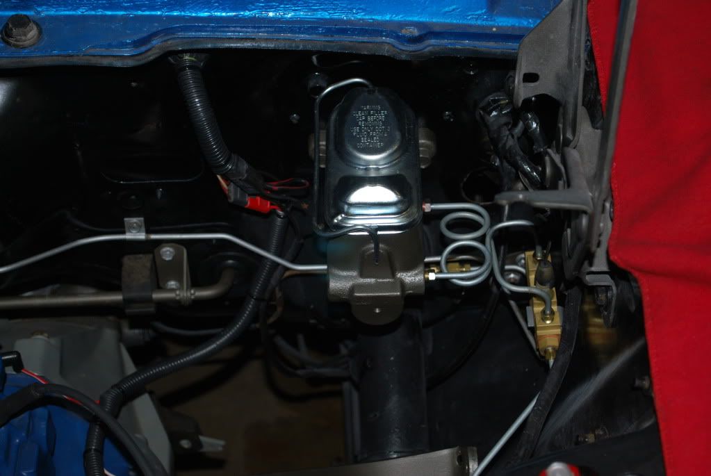
I've had most of the parts for a couple of years, waiting for the time, place and motivation. So, already have drums & hardware for the front, but I wish I'd realized back then how relatively inexpensive a front disc upgrade would've been.
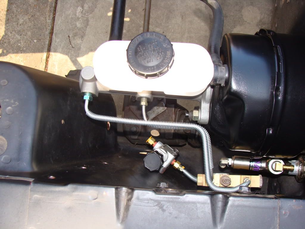
Thanks for the link, tbone6, stainless pre-bent
lines are on the way. Things look pretty rusty and, after making tranny
lines from scratch, I'd rather not do the bending for
this project.
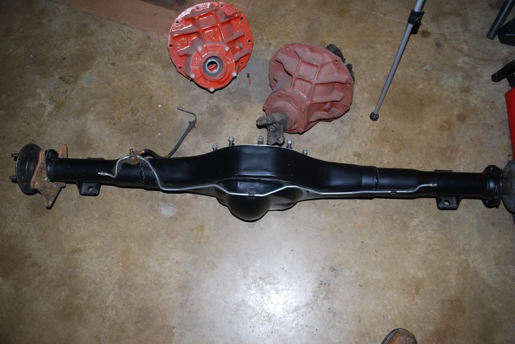
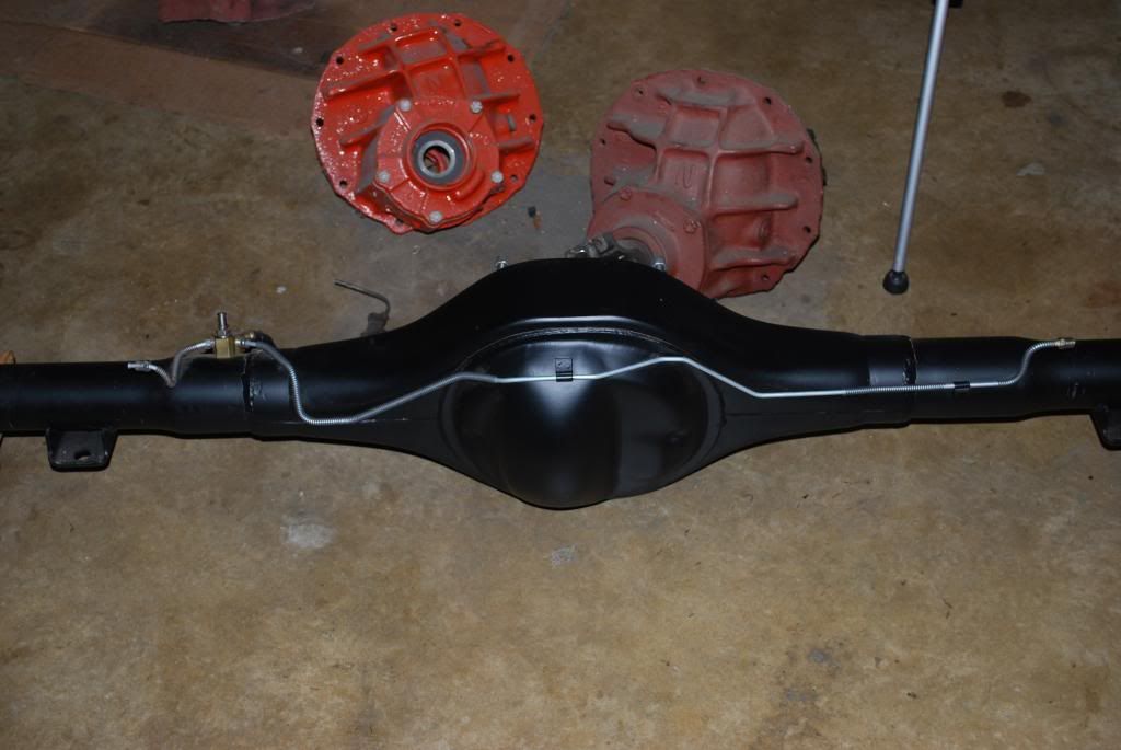
Ultraranger, I'm hoping the rearend checks out okay--I really don't want to go full teardown. Wait, perhaps "don't want to" isn't quite correct...

..."not ready for all that" is more appropriate.

(BTW, found your post this Sunday on flaring, tooling and fittings particularly informative.)
The wasps are all dead now & truck washed out. Will brush off some underside grime before rolling into the shop hopefully tomorrow.
Thanks again!
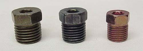
The standard fitting size for a 3/16" diameter
brake line tube is 3/8"-24. A pair of 3/8"-24 fittings will come on the straight lengths of
brake line tubing you get from the parts stores and you can also purchase the 3/8"-24 fittings individually from the parts stores. Ford also used specialty
brake line fittings for 3/16" dia. tubing that came in 7/16"-24, 1/2"-20 & 9-16"-18 thread sizes. Very few if any parts stores will carry any of these last (3) fitting sizes and is more than likely something that would have to be special ordered off the internet.
 Double flaring brake line tubing
. (sorry that some of the following photos are out of focus but, I think you will get the general idea of what I'm trying to explain here).
If you're fabricating your own
brake (transmission or fuel)
lines, and assuming you have cut the tubing off to length with a tubing cutter, it will leave a burr or ridge around the inside diameter of the tube. This burr needs to be removed to open the I.D. back up.

This can be done with a reamer designed for tubing;

...or, you can use a small diameter drill bit to ream the burr.

Take a flat file and square up the tip of the tubing.

Place the file on the tip of the tubing end at approximately a 45-degree angle to chamfer the outer edge.

After the first two processes, you should have a piece of tubing with smoothly chamfered inner and outer diameters.

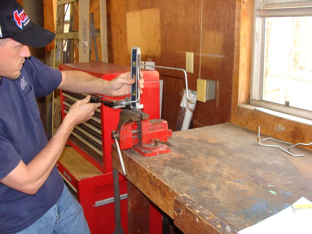
Now, it's time to begin double flaring the tubing. Double flares are designed for 45-degree flares. The 1st stage of the double flare process involves the flaring 'button.' You will notice there is a 'step' on the button. Place the tubing into the flaring bar and adjust the tip of the tube to stick out above the surface of the flaring bar the same height as the thickness of the step on the button.

Once you have the height of the tube set to the thickness of the step of the button on the flaring bar, insert the stem of the button into the end of the tube and then place the flaring yoke directly over the button and the end of the tube. --It's very important that the button/yoke are not off to one side or the other on the tubing end. They need to be directly centered, inline, over the tubing end. If it's off, you will get a deformed flare and it will be highly likely that it will be hard to make the line seal off when it's installed or, it may not seal at all.

Tighten the flaring yoke down until the button bottoms out against the surface of the flaring bar.

Remove the yoke and remove the button. Place the flaring yoke back on the flaring bar and tighten the yoke down on the end of the tubing. As in the 1st stage, make sure the flaring yoke is directly centered over the end of the tubing. WARNING! Unlike the 1st stage of the flaring process, DO NOT CRANK DOWN TIGHTLY ON THE FLARING YOKE DURING THE 2nd STAGE OF THE PROCESS!! You just want to get the 2nd stage of the double flare well-formed. You do not want to flatten the 2nd stage of the flare out against the 1st stage of it. Let the line fitting do the final compression of the double flare when you tighten the line assembly into its port.

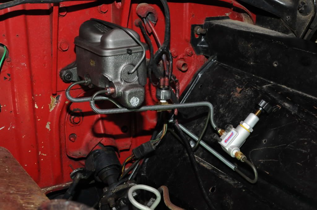
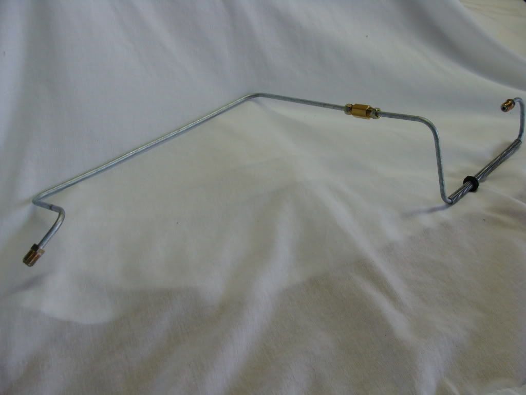
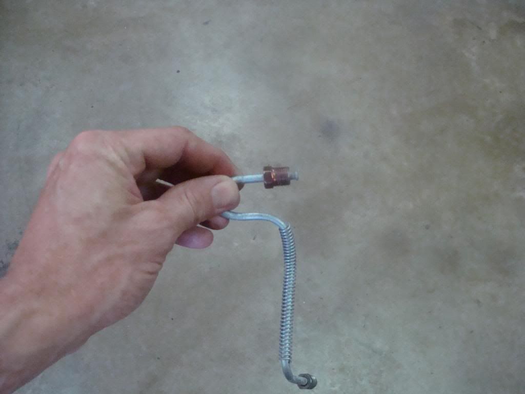
...Presto! One double flared 3/16"
brake line...

...ready to be hooked up to the port of a MC,
brake valve or the end of a flexible
brake line hose. (NOTE! IF you are flaring a line that is not straight, be sure to install your line fitting BEFORE you start flaring the line!)

The process shown above is more or less the 'difficult' way to double flare
lines. If you're lucky enough to have a hydraulic flaring/double flaring tool set (or a friend that has one), like this Mastercool set (part number 71475), your life will be a LOT easier. It's much faster than the manual flaring bar/yoke setup and produces production-quality flares/double flares each & every time. I paid just under $300.00 for this set. That may seem very expensive to some but if you've ever used one, you'll quickly learn that it's worth every penny. --NOTE; All preliminary line end deburring prep procedures still apply when using the hydraulic flaring tool.
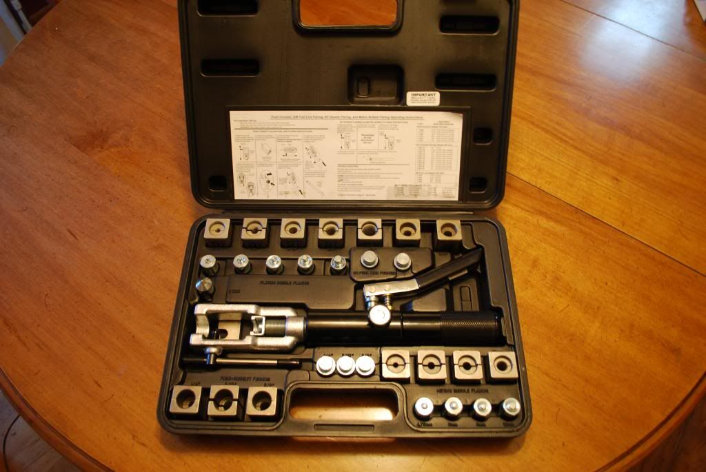
Hydraulic flaring ram, tubing dies, flaring die & double flaring die.

Place the tubing into the tubing dies so that the tip of the tube is even with the outer edge of the dies.

Place the tubing/dies into the flaring ram and tighten into place.

Take the 1st stage flaring die...

...and place it into the end of the flaring ram.

Close the valve (the round knob on the side of the handle), twist the handle of the ram clock-wise to run the die up against the end of the tube and then start squeezing the lever on the handle 'til you feel the die bottom out.

Remove the 1st stage die and insert the 2nd stage die.

As with the manual flaring tools, don't crank down hard on the 2nd stage. You don't want the double flare flattened completely out. Again, final compression of the double flare should come when the line is tightened into the object it's going to be installed on.
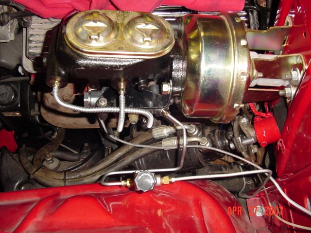
One production-quality double flare!

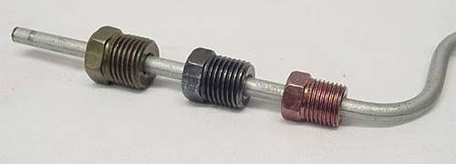
In addition to SAE double flares, the Mastercool hydraulic set will also make ISO metric bubble flares. If you were installing a modern MC (aluminum body with plastic reservoir) in a vehicle but still using the SAE
brake valve, you could double flare one end of the tube and put a bubble flare on the other end. In this photo, I've installed a metric bubble flare and fitting, in the foreground of the example tube, and an SAE double flare and fitting on the opposite end.

...same tubing example, from above, bent into a 90. (SAE double flare/fitting on the left, ISO metric bubble flare/fitting on the right).

If you're going to fabricate your own
lines, the temptation for most people is to put as little money possible into the fabrication tools. The old adage of; "you get what you pay for," definitely applies to line fabrication tools. Cheap line flaring tools generally results in hit-or-miss flares that may or may not seal off.
It's also tempting for many to buy the cheap 3-in-1 tubing benders. A 3-in-1 will never make the quality bends that an actual, quality, dedicated bender will make. --by, "dedicated," I mean a tubing bender that will only bend one diameter of tubing. As tubing reduces in diameter, the bending radius of the bender should become smaller (tighter) too. Pretty much all of the 3-in-1's I've seen had the same bending radius for all three tubing diameters. That would result in sloppier bends, if the radius of the bender is the same for all three tubing diameters.
I have 3 (dedicated) Imperial brand benders, one each for; 3/8", 5/16" & 1/4" diameter tubing. My 3/16" tubing bender (the black bender in the following photo) is a Rigid brand. (the flaring bar and silver tubing cutter is also an Imperial brand).
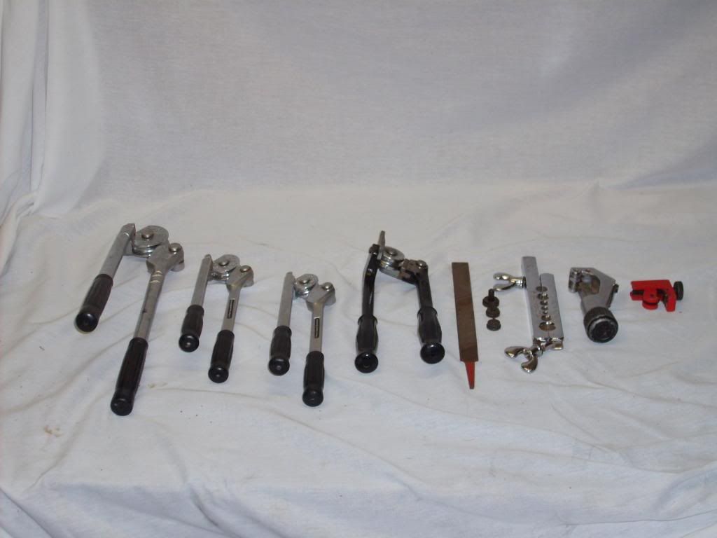
You would also be wise to invest in some decent flare nut line wrenches.

...a tip that could make your life (or someone else's) a lot better down the road; Many of us have experienced
brake line fittings that would simply not break loose, even with a flare nut line wrench. It usually requires Vise-Grips which ends up chewing up and rounding off the flare nut fitting. Once you get the carnage apart and get ready to install the new line/fitting, take a moment to put a little Anti-Seize on the threads of the line fitting, just prior to connecting the fitting to the port. A little Anti-Seize goes a long way. Use it sparingly and don't coat the first two leading threads of the fitting. This will keep the Anti-Seize from getting into the
brake system. I've done this for many years and have never had a problem of the Anti-Seize contaminating the
brake fluid. Sooner or later, you will have to replace a MC,
brake valve or
brake hose. Coating the fitting threads means you will not destroy the fitting, the next time around. --the same can be done to the bleeder screws on a
brake caliper or wheel cylinder.

Bare threads.
Applying a thin coat of Anti-Seize on the
brake line fitting, --leaving the 1st two leading threads uncoated.

Coated fitting threads, ready to be installed. --won't have to fight with this fitting to get it loose some years down the road.

...with a little practice, you can make your own
lines.